Intermediate pumping stations
Sewage intermediate pumping stations are comprehensive tank and pump systems equipped in hydraulic fittings and a control system. The goal behind the pumping station is to transport the industrial and municipal sewage, drain water and other water across large distances or altitude levels (e.g. to another tank). In the majority of case, sewage from one or more households flow down directly to the intermediate pumping station tank and then, using a system of submersible pumps, is pumped to a collecting well situated on the main intercepting sewer or directly to a water treatment plant. The following types of pumping stations can be distinguished with respect of their intended use: network, household, municipal, industrial, zone and those working within the water treatment plant technological system.
The pumping stations make it possible to connect sewage systems to facilities located in a considerable distance from intercepting sewers without the necessity of performing extensive ground works for the installation and make it easier to install a sewage system on hilly areas (pumping-type installation). The possibility of connecting facilities situated in pits and pumping raw sewage with the use of pumps with a vortex or shredder constitute yet another advantage of the device.
Tanks
Cylindrical, tight tanks with a bottom, lid and manhole suited for the foundation soil constitute the pumping station housing. The choice of tank material depends on its height, soil conditions and customer preferences.
The following materials can be used to make the tanks:
- High-density polyethylene (PEHD) with circumferential rigidity of 4 kN/m2, with its diameter varying between 600-3000 mm and a maximum height of 7000 mm.
- Polyester resins (GRP - Glass-reinforced plastic) with a diameter varying between 800-2400 mm and a maximum height of 7000 mm.
- B45 reinforced concrete with a diameter varying between 1000-3000 mm and a maximum height of 7000 mm.
- Polymer concrete with a diameter varying between 1000-2000 mm and a height of 1000-10000 mm.
Moreover, there can be a technology platform made of stainless steel or GRP. This solutions ensures easy access to pumps and fittings.
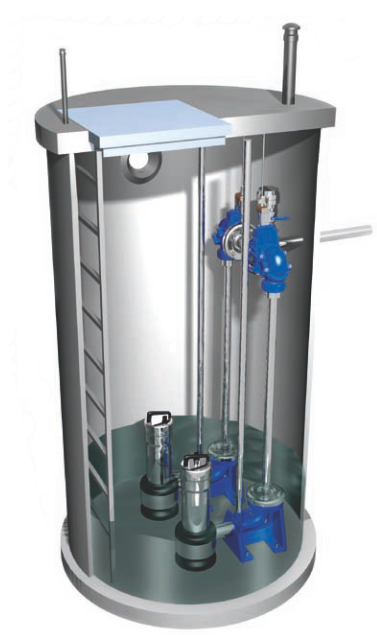
Pomps
The pumping system can be equipped in one or two submersing pumps connected with the pumping installation with the use of elbows.
The pumps are installed by sliding them on a chain on a slideway made of stainless steel. The pump seals automatically behind the elbow thanks to an appropriately construed pump catch. Elbows and slideways are fixed into the tanks whereas the pump is movable.
We employ pumps from both Polish and foreign manufacturers:
![]()
![]()
![]()
![]()
![]()
![]()
![]()
![]()
![]()
![]()
![]()
Hydraulic system:
Pumps made of stainless steel or PEHD. Fittings (non-return ball valves, flanged and gate valves) made of cast iron. A manhole ladder made of stainless steel or aluminum has been installed in the pumping station.
Get to know our On-site waste water pumping station offer.
![]()
- Ramowy Harmonogram Realizacji Rozliczeń (.docx / 17Kb)
............................................................................................................................................................................... - Techniczno - Organizacyjne warunki realizacji zadania (.pdf / 470Kb)
............................................................................................................................................................................... - Wytyczne montażu i eksploatacji (.pdf/ 480Kb)
............................................................................................................................................................................... - Zasady gwarancyjne (.pdf / 410Kb)
............................................................................................................................................................................... - Zgłoszenie gotowości do montażu wyposażenia (.pdf/ 411Kb)
............................................................................................................................................................................... - Zgłoszenie gotowości do rozruchu(.pdf / 412Kb)